Transducers, gauges, sensors - Information portal © 2011 - 2025 Use of material is possible by placing an active link


Home >> Publication >> the Semiconductor measuring transducers.. strain gauge
русский / english

• Information about various converters and sensors of physical quantities, parameters of various physical processes is presented.
• Electrophysical properties and effects in various electrical materials.
• Theory, experimental results, practical application
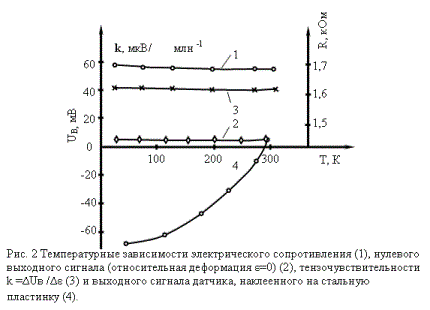
Results over of measuring of some descriptions of strain gauge are further brought. On a fig. 2 dependences are shown on the temperature of electric resistance (1), zero output signal(2), strain sensitivity k =ΔUв /Δε (3) and output signal of sensor, glued on a steel plate (4). The last watches thermal tensions.
On a fig. 3 dependence of output tension of Uв is shown on the size of the attached deformation. A chart testifies to good linearness of description. tensosensitivity of this party of sensors, as be obvious from a chart, 42 мкВ/mln^-1 is equal.
Research of error of measuring of deformation is conducted also by means of strain gauge in the conditions when the axis of base of sensor does not coincide with direction of main deformation of object. On a fig. 4 direction of main deformation of e1 beam and layout of sensors chart is shown on a beam. Sensors were fastened by means of glue of БФ- 2. Axis of base of sensor 1 coincides with direction of main deformation of e 1, sensor 2 located under the corner of 30° to e 1, sensor 3 - under the corner of 45° and sensor 4 - under the corner of 90° (coincides with main deformation of e 2). All sensors are taken from one party, made in one technological mode.
The size of the measured deformation of eэ is certain with the use of formula (1). Calculation deformations which were used for comparing to got experimentally are certain on formulas, taken from [2]:
εφ = [(ε1 + ε2 ) / 2] + [(ε1 - ε2 ) / 2] cos2 φ
where φ is a corner between direction of ε1 , and direction which deformation settles accounts for. Deformation of ε2 is expected on the formula of ε2 = -- με1 (where m is a coefficient of Puassona). Results over of research are brought in a table 2.
The most difference of εφ from εэ is observed for φ =30° and makes a size 6,% that does not exceed the error of experiment. Results testify to practically absent transversal strain sensitivity sensors.
On a fig. 5 results over of one research are brought of sensors in the magnetic field at Т= 4.2 К. Curve (1) corresponds to the size of seeming deformation at affecting of magnetic-field the undeformed sensor (ε =0), and curve (2) on preliminary deformed to ε =1·10^3 млн^-1. the Field of 7 Тl results in an error approximately 3%.
- 2 -

See also:
CONVERTERS, GAUGES, SENSORS
Information, news, advertising


