Transducers, gauges, sensors - Information portal © 2011 - 2025 Use of material is possible by placing an active link


Home >> Magnetic field >> Wo is Hall sensor? Physics-technical bases of work of measuring transformer of magnetic-field - sensor of Hall
русский / english
• Information about various converters and sensors of physical quantities, parameters of various physical processes is presented.
• Electrophysical properties and effects in various electrical materials.
• Theory, experimental results, practical application
Hall sensor. Description, device, principle of operation
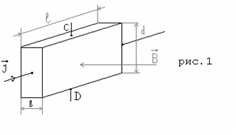
A Hall sensor is a device with which the magnitude of the magnetic field is measured using the Hall effect. The Hall sensor consists of a solid-state rectangular plate to which four electrical terminals are connected. Schematically, the sensitive element of the Hall sensor is shown in Fig.1. The Hall effect is as follows. Let the sample have the shape of a rectangular plate with length l, width d, thickness b (see Fig. 1).
The Hall effect and the physical basis of the Hall sensor. If an electric current I is passed along the sample, and a magnetic field B is created perpendicular to the plane of the plate, then an electric field will arise on the lateral planes of the plate in the direction CD, which is called the Hall field. In practice, as a rule, the Hall field is characterized by a potential difference, which is measured between symmetric points C and D on the lateral surface of the sample. This potential difference is called the Hall potential difference Uhal or Hall EMF εhal.
In the classical theory of conductivity, the Hall effect is explained by the fact that in a magnetic field, the Lorentz force acts on moving electric charges, the magnitude and direction of which are determined by the vector equation:
F = e [VB] ( 1 ),
where B is a vector of induction of magnetic-field,
V is a rate of movement of charges,
е is a charge of transmitters of current taking into account a sign.
In our case, V is perpendicular to B and the electric field of the Hall is determined by:
Ehal = V B ( 2 ),
is associated E.M.F. Hall of εhal, or hall potential difference as follows:
εhal = Uhal = Ehal d= VBd ( 3 ).
Strength of current which flows through unit of area of cross-sectional of standard is equal to the closeness of current:
J = enV ( 4 ),
where п is an amount of transmitters of current in unit of volume of standard (concentration of transmitters of current). From here strength of current:
I = jbd=enVbd ( 5 ).
That enables to write down:
V = I / enbd ( 6 ),
εhal = IB/ enb ( 7 ).
Thus, E.M.F. Hall (or Uhal) proportional to strength of current, induction of magnetic-field, and inversely proportional to the thickness of standard and concentration of transmitters of current in him.
Often recorded:
εhal = R⋅ IB/b ( 8).
Where the coefficient R = 1 / ne is the Hall constant, which, for example, for semiconductors has a value from 10 - 10∧5 cm3/Cl.
How the Hall sensor works. For fig.2 shows the characteristic dependence of Uhal on the magnetic field at a constant supply current.
In the absence of a magnetic field, the Hall E.M.F. should be zero. However, as a result of various side effects (for example, an insufficiently symmetrical placement of the sensor's measuring electrodes), the measuring device may show some difference in the Uo potentials at the Hall Sensor output, even in the absence of a magnetic field. To eliminate the associated errors, the value of Uo should be subtracted from the measured potential difference in the magnetic field.
One of the main characteristics of the Hall sensor is the sensitivity:
g = ΔUhal/ ΔB.
The hall sensor sensitivity specified in its passport data is used to determine the value of the measured magnetic field induction:
B = Uhal / g.
It should be borne in mind that the Hall probe measures the perpendicular (to the plane of the sensor) component of the magnetic field vector. Therefore, if you need to measure the maximum value of the magnetic field, you need to orient the Hall sensor accordingly.
For the manufacture of Hall sensors, InP, InSb, GaAs, Ge, and Si semiconductors are most often used.the use of semiconductors is due to the fact that due to the high mobility of current carriers, they have a high sensitivity to the influence of a magnetic field. The sensitive element of the Hall sensor can be made of either bulk material or based on semiconductor films on insulating substrates. The Hall sensor can have a different shape, which affects the linearity of the output signal's dependence on the magnetic field, and the sensitivity. The dimensions of modern Hall sensors can not exceed 1x1x0. 5 mm, the power supply currents are usually 1-100 mA (depending on the input resistance of the sensor), the sensitivity can reach 1000 mV / TL or more, the operating temperature range is from -270 °C to 200 °C. In addition to sensitivity, one of the main parameters of Hall sensors is the temperature dependence of the sensitivity, input resistance, and initial output signal Uo. For good Hall sensors, they should be insignificant.
See also:

Magnetic fields
Measurement of magnetic fields, measurement principles. What is a Hall sensor, parameters, formulas. Slightly different explanations of the basics of the Hall sensor can be found at the links on the page
See also:
CONVERTERS, GAUGES, SENSORS
Information, news, advertising


