Transducers, gauges, sensors - Information portal © 2011 - 2025 Use of material is possible by placing an active link
Home >> Load cells, strain gauges >> Measurement of mechanical strain ( stress ) using a strain gage
ðóññêèé / english
• Information about various converters and sensors of physical quantities, parameters of various physical processes is presented.
• Electrophysical properties and effects in various electrical materials.
• Theory, experimental results, practical application
Measurement of mechanical strain ( stress ) using a strain gage
Examined the device, the operating principle and method for measuring the deformation of an object using metal foil strain gages and semiconductor strain gauges. The example of the measurement.
This gauge is a device electrical resistance of which changes when it is deformed. This change in resistance due to the magnitude of the mechanical deformation via ε gauge factor:
k = ΔR/Rî⋅ ε,
where Ro - initial electrical resistance strain gauges, ΔR = Rε - Ro - the value of the change in resistance under the influence of deformation, Rε - The value of electrical resistance strain gages.
Currently, the most widely to measure the deformation of used foil ( foil material metal) and strain gages for specific tasks semiconductor. The advantages and disadvantages of both types of strain gauges are well represented in the literature. The main advantage of semiconductor tenzorezitorov is their higher (up to 100 times) tensosensitivity, but at the same time, they are more fragile, rigid, higher temperature dependence of the parameters. High tensosensitivity semiconductor strain gauges due to changes in the band structure of the semiconductor material under the influence of mechanical stress and thus the strong dependence of conductivity ( resistance) of the deformation. While in metal strain gages provided tensosensitivity changes size sensor ( foil ).
Foil strain gages are distinguished for its intended purpose - to measure the uniaxial strain, the strain distribution for different temperature ranges, the size and shape of the lattice ( the form of an electrically conductive foil ) on the values of electrical resistance, as well as some other parameters.
Fig.1
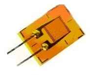
One of the easiest foil strain gauges is shown in Figure 1. Construction of the strain gauge such that it reacts ( changes its resistance) substantially only when the deformation is directed ( applied ) along the axis of the lattice strain gage or component complexity arises deformation distributed in the direction (this is called " longitudinal tensosensitivity " ). And the change of resistance is proportional to the longitudinal (or part of the complex ) and the strain associated with its value of the coefficient k. It should be noted that there is a transverse tensosensitivity, i.e. sensitivity to deformation directed perpendicular to the base ( longitudinal axis) of the strain gauge, but it is negligible, as a rule, to foil gages close to zero, while the wire does not exceed 1% of the longitudinal.
The main reason for the change in resistance foil strain gages under the influence of a change in the size of conductive grid. As is well known electrical resistance of materials is determined by the relation:
R = ρl / S,
where ρ - the resistivity ( wire material , foil strain gauge ). l - length ( wire lattice foil ), S - area of cross section ( wire, strip foil ). The resistivity of the deformation hardly changed, and change l and S. When tensile deformation resistance will increase, decrease compression . In the process of using strain gages is taken into account for determining the sign of the deformation of the object.
To foil strain gauges gauge factor depends on the foil material , and its value is in the range k = 2-4 and specified in the data sheets and descriptions of strain gauges attached to the party. The electric resistance is typically 50 ohms.
Fig. 2
To measure the deformations of the object gage mounted ( glued ) at the object, which must be measured deformation. Figure 2 shows the strain gauge glued to the test object. In order to be possible to accurately measure the deformation of the object , it is necessary above all to deformation relatively unscathed from the object passed on to the bars of the strain gauge. This is achieved by selection of a suitable binder ( adhesive) and mounting technology . The main requirement to the binder is the lack of plastic deformation in the working range of the use of the strain gauge. The optimum binder technology and work with it are specified in the technical literature to lots of strain gauges. It is often used as the binder adhesives such as BF -2.
Resistance listed in the data sheet and measured after the installation of the strain gauge to the object may be slightly different - in the polymerization bonding can occur lattice strain gages. With accurate measurements it is necessary to take into account.
Then, after the installation of the strain gauge to the object in the mechanical testing of the object measured the electrical resistance of the strain gauge. For example, if strain gage gauge factor k = 2, the initial resistivity ( specified in the data sheet measured after the installation of the strain gauge to an object ) Ro = 200.1 ohms, when mechanical loading facility Re = 200,9 ohms, the amount of mechanical deformation ( in stretching this case ) at a strain gage mounted in the direction of its base is equal to:
ε = ΔR/kRî = (Rε - Rî)/kRî = 0,002 = 2⋅10^3 mln^-1 = 2⋅10^3 URS.
That is, magnitude of the strain is 0.002. The values of relative strain is sometimes expressed in URS - a unit of the relative strain, which is equal to one millionth ( a millionth part - mln ^ -1) units of deformation.
In practice, the measurement of deformations using special equipment to automate measurements, more sophisticated measurement technology for maximum precision , calculation errors on certain procedures, etc.
If you want to determine the mechanical stresses of the object at the point of strain measurement, the use of mechanical deformation ε of a certain connection with the mechanical stresses σ:
σ = εE,
where E - Young's modulus ( elasticity ) of the material object.
The method and sequence of measurements of mechanical deformations using a semiconductor strain gauge is basically almost the same as described above for the foil.

See also:
CONVERTERS, GAUGES, SENSORS
Information, news, advertising
