русский / english

Fig. 4. The dependence of the collected on the electrode charge voltage on a discharge gap for large and small primary ionization:
/—area ionization chambers; //—area proportional gain; /// the region of limited proportionality; IV— region of self-discharge or the Geiger region; V— region of a continuous discharge.
How does the ionization chamber.
If the electric field is such that electron up to the next collision will have time to gain energy equal to the ionization potential of the gas, the collision will occur, the act of ionization, i.e. electron shell of the atom released electron. This "secondary" electron together with the "primary" field and re-dispersed in the following collisions, each of them ionize the atoms, creating new "secondary" electrons.
Their number increases rapidly, like the formidable snow avalanches, sliding down the steep slopes of the mountains. This process is therefore called the process of formation of electronic avalanches. In this process, as the voltage increases the quantity of electricity per pulse increases rapidly (the phase II in Fig. 4).
In its motion to the filament of the electron formed by the external ionizer creates in its path a large number of new ions and electrons. Obviously, the quantity of electricity per pulse in the area of stress // will be many times more quantity of electricity per pulse in the area, how many times will "multiply" the primary electron. The electric current in the meter as would be multiplied, intensified, as well as for the photoelectron multiplier.
The gain reaches tens of thousands of times. The number, which increases the amount flowing through the electricity meter compared to a plot of stress /, is called the gas amplification factor. The value of the coefficient of gas amplification can vary between units, in the case where the counter operates in the ionization mode of the camera (the part of the curve), and approximately to several thousand in the end of the segment //. On this part of the value of the coefficient of gas amplification does not depend on the number of primary electrons. Regardless of whether the initial impulse of γ-quantum, α-particle, or β-particles, it increases in a constant number of times.
So here, as well as in the chamber, the magnitude of the impulse is proportional to the ionizing radiation, whereby this region is called the region of proportional gain. A counter operating in this region, called proportional counter. Proportional counters are characterized not only by the fact that the value of the coefficient of gas amplification in them does not depend on the initial number of pairs created by an external ionizer, and also the fact that the discharge in them is terminated immediately after the cessation of external ionization. This type of discharge is called non-self-discharge. As the voltage increases the gas amplification factor increases.
With further increase of the voltage U2 higher the gain begins to depend on the value of the initial ionization. For pulses resulting from the passage of ionizing particles with large capacity, the amplification factor smaller than that of pulses from particles with low ionizing ability is Why the region stresses from U2 to U3 is called the region of limited proportionality.
If you continue to increase the voltage on the meter, the quantity of electricity per pulse does not depend on the value of the initial ionization. In this case, the meter enters into mode of self-discharge, i.e. the discharge which, if not to accept special measures, the resulting discharge does not stop after removal of the external ionizer, i.e. the category itself supports. The voltage region from U3 to U4 is called the Geiger region, a counter operating in this mode, the Geiger - Mueller or gas-discharge counters.
From these counters, the value of a pulse voltage on the load resistance does not depend on the initial ionization. Consequently, such counters are unable to serve directly to measure the ionizing action of radiation. But these counters have a huge sensitivity: enough in the meter to receive the at least one electron as it is born the electronic avalanche and in the external circuit will pass a current pulse.
If the voltage on the counter to raise above the point U4, the counter enters the field of continuous discharge becomes unfit for registration of ionizing particles.
Thus, depending on the applied voltage, the counter can operate as ionization chamber, a proportional counter and gazorazryadnaya Geiger - Muller. However, in practice they represent three types of different devices with different designs and depending on the purpose apply one or the other device.
Sensorse.com: How the ionization chamber works
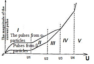
Fig. 3. The circuit and operation of the ionization counter. How the ionization chamber works
How does the ionization chamber
Consider the device shown in figure 3, consisting of a metal cylinder, the axis of which the insulators taut wire thread. Such a device we will call the gas-discharge counter. The figure shows a cross-section of the counter. The cylinder is connected with the negative pole of the battery and therefore call it a cathode; the thread through the load resistance, with the positive pole and will call it the anode.
If through the working volume of the counter will be ionizing particle, then its motion will be positive ions and electrons, which under the action of an electric field move to the electrodes: electrons on a thread, the ions at the cylinder. In the external circuit will pass a current pulse that forms the impetus of the voltage drop on the load resistance. This voltage pulse can be fixed by using a registered device.
Consider how it will change the quantity of electricity in the current pulse depending on the value applied to the counter voltage. Initially, under very small stresses, as well as in the ionization chamber, the quantity of electricity per pulse will correspond to an incomplete number of electrons that have survived to the thread, as some of them due to the weakness of the electric field along the way you can recombine. Therefore, with increasing voltage the counter is incremented and the quantity of electricity per impulse. At a certain voltage all of the electrons formed in the ionization of radioactive particles that will get on the thread, and the quantity of electricity per pulse increases. There comes a saturation current. This corresponds to the horizontal part of the curve in Fig. 4.
The quantity of electricity per pulse in this area is determined only by the primary ionization power of the ionizer. The more the capacity, the more quantity of electricity per pulse. So a α-particle has the greatest ionization power, corresponds to the upper curve. The area of strain from 0 - U1-area, called the ionization chamber region /, since the counter works as an ionization chamber, i.e. the amount collected on the electrodes of the charge equal to the total charge of the electrons formed in the ionization process.
When the voltage of the counter exceeds a certain value the U1 at which the tension (force) of the electric field increases so that the electrons acquire a speed sufficient for the production of impact ionization, the quantity of electricity per pulse increases due to additional ionization of a gas by colliding electrons. By slowly increasing the voltage this process of impact ionization first occurs only around the filament, where the field strength is greatest. We know that ionization of an atom by an electron can occur only in the case when the energy of the electron will be equal to or greater than the ionization potential of the gas in which it moves. At every meeting with a neutral atom, the electron loses most of its kinetic energy.
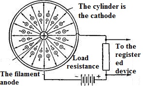
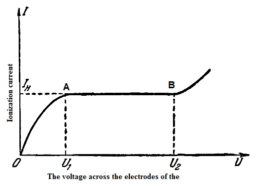
Fig. 2. The current-voltage characteristics of the ionization chamber.
How does the ionization chamber
The curve of dependence of ionization current camera on the magnitude of the applied voltage is called the volt - ampere characteristics. On the site characteristics from a to B is a discharge gap is the so-called silent discharge.
Ionization chambers are usually in the region of current saturation. Since the magnitude of this current is proportional to the number of ions formed, it can serve as a measure of the ionization ability of the radiation.
Depending on the use of ionization chambers are of two types. Camera used for measuring the total ionization caused by the passage through its displacement of a significant number of ionizing particles, called an integrating ionization chambers. In a camera, if it works in saturation region, after a very short period of time after commencement of radiation is a balance between the number of pairs of ions produced in the chamber per unit time and the number of pairs of ions going to the electrodes at the same time. The magnitude of the saturation current is equal to the product of the number of pairs of ions produced per second per cubic centimeter of chamber, its displacement and the charge of each ion. Therefore, the current saturation value can serve as a measure of the radiation dose. The latter is proportional to the number of ion pairs formed per cubic centimeter per unit of time.
The second type are controindicazione camera that can be used to check and determine the ionization ability of any one ionizing particle (e.g. a-particles) trapped in the working volume of the chamber.
From the ionization chamber to the Geiger - Muller. Radioactive radiation
Fig. 1. The principle of ionization chamber. How the ionization chamber works
How does the ionization chamber
With the increase applied to the plates voltage increases the strength of the electric field and increasing the number of charged particles, not having time to recombine, falls on the electrodes. The strength of the current in the external circuit increases (Fig. 2, from O to A).
Finally, at some voltage U, the electric field strength increases so that all charged particles formed by an external ionizer in the working volume of the chamber will get on the electrodes. In this case, the current in the external circuit is determined only by the ionization ability of the radiation. If the ionization ability of the radiation does not change, then the current in the circuit chamber flows unchanged (area And curve). This current is called the saturation current of the camera.
With a further increase in the voltage at point U2, the current flowing in the circuit of the camera starts to rise again, first slowly, then faster and faster (the portion of the curve above the point). This is because when the voltage above the point U2, the strength of the electric field within the chamber increases so that the electrons under the action of its get velocities sufficient to ionize neutral gas atoms at their meeting. Therefore, the current in the external circuit is determined by the total number of charges formed under the influence of external ionizer and under the action of ionization electrons struck inside the working volume of the chamber.
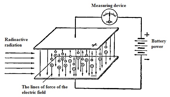
How does the ionization chamber
(How the ionization chamber works)
In the simplest case, the ionization chamber is a device of two metal plates, insulated from one another and separated by a gas gap. Any air condenser can act as ionization chambers. The space between the plates is called the working volume of the chamber. If the plate to apply a constant voltage, the space is formed between the electric field whose lines of force are directed from the positive plate to the negative. On electrically charged particle placed in an electric field, will act in force, under which it will move in a path coinciding with the direction of the power lines. The direction of motion of positively charged particles coincides with the direction of the field lines. Negative particles move in the opposite direction, i.e., towards the electric field lines.
Consider the processes occurring in the working volume of the ionization chamber. In the absence of voltage on the electrodes of the chamber, the ions and electrons formed in the working volume as a result of radioactive radiation, are moving randomly along with the neutral atoms, some of them rekommenduetsja reaching the electrodes, the part of the accident falls on the electrodes. If now the electrodes to apply a small constant voltage, under the influence of an electric field ions and electrons acquire directed movement corresponding to the field lines (Fig. 1). The electrons move to the positively charged plate is the anode, while positive ions to the negatively charged plate the cathode. The speed of motion of a heavy positive ions in the thousands and tens of thousands of times less than the speed of light electrons.
At low electrode voltage field between the weak and the particles are moving slowly. So most of them are not reaching the electrodes, recombines, i.e. turns into neutral gas particles. As a result, in the external circuit the current will be very small.
The strength of ionization current is equal to the total electric charge brought by the charged particles to the surface of the electrode during one second. The more ions going to the electrodes, the more current. This current is recorded using any electrical appliance connected to the circuit of the camera.
Transducers, gauges, sensors - Information portal © 2011 - 2025 Use of material is possible by placing an active link
• Information about various converters and sensors of physical quantities, parameters of various physical processes is presented.
• Electrophysical properties and effects in various electrical materials.
• Theory, experimental results, practical application
See also:
