Transducers, gauges, sensors - Information portal © 2011 - 2025 Use of material is possible by placing an active link
русский / english
Home >> Ionization transducers >>> Ionization measuring transducers
• Information about various converters and sensors of physical quantities, parameters of various physical processes is presented.
• Electrophysical properties and effects in various electrical materials.
• Theory, experimental results, practical application
Ionization measuring transducers
For Fig. 1 shows the block diagram of one of the ionizing transducers with a radioactive isotope. The device is designed for continuous measurement of the thickness of a moving tape or rolled steel.

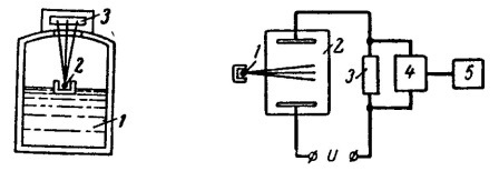
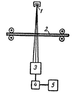
Fig. 1. Scheme of ionization transducer for measuring the thickness of the tape.
The principle of operation of the device is as follows. Radioactive radiation of isotope 1 is partially absorbed by product 2. The amount of energy obtained by the indicator 5 depends on the material and thickness of the product. Indicator 3 via amplifier 4 is connected to the measuring mechanism 5 barred in the values of the measured value.
Fig. 2. Scheme of the ionization level gauge.
Fig. 3. Scheme of the device for measuring the gas pressure.
For Fig. 2 the scheme of the device of the level transmitter working on the same principle is shown.
On the surface of liquid 1 floats float 2 with a radioactive isotope. Indicator 3, which receives radiation, is located above the float. When the liquid level changes, the distance from the radiation source to the indicator and, consequently, the amount of energy received by the indicator changes.
For Fig. 3 the block diagram of the gas pressure meter is given. Under the influence of radioactive radiation of isotope 1, ionization of the gas occurs in vessel 2. Depending on the gas pressure, the ionization intensity and the ionization current passing through the circuit under the applied voltage U. the Measuring mechanism 5 is switched on via amplifier 4 to resistance 3, the voltage drop on which is created by the ionization current.
A similar device have ionization gas analyzers.
See also:
CONVERTERS, GAUGES, SENSORS
Information, news, advertising
