Transducers, gauges, sensors - Information portal © 2011 - 2023 Use of material is possible by placing an active link
Voltage stabilizer. Scheme, description
To supply a variety of transducers, devices, electronics ( CEA), in most cases apply voltage stabilizers. Voltage stabilizer is a device designed to automatically maintain the receiver inputs electricity voltage constant value regardless of fluctuations in the mains voltage and the load.
The principle of operation of voltage stabilizers are divided into parametric and compensation. To apply the parametric stabilizers in which the control element acts on the controlled variable in order to bring its value to the value of a predetermined value without taking into account the difference between a predetermined value and regulated.
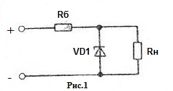
The simplest and at the same time the most common parametric stabilizer is a stabilizer feature uses the current-voltage characteristics of the Zener diode. It is a voltage divider comprising a ballast resistor Rb and zener VD1 ( Fig. 1).
When calculating the parameters of the elements of parametric stabilizer, previously known quantities are the limits of variation of the supply voltage; zener voltage equal to the output voltage, the minimum and maximum current stabilization, the dynamic resistance of the zener diode.
Home >> Physical basis of transformation of measureable parameters >> Voltage stabilizer. Scheme, description
русский / english
• Information about various converters and sensors of physical quantities, parameters of various physical processes is presented.
• Electrophysical properties and effects in various electrical materials.
• Theory, experimental results, practical application
Fig. 1. Parametric stabilizer
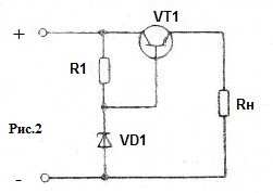
Fig. 2. Parametric stabilizer with a transistor
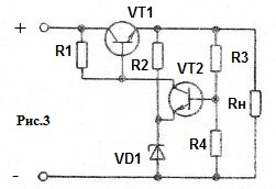
Fig. 3. Expansion Kit with sequential switching transistor
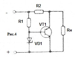
Fig. 4. The shunt regulator
Ballast resistance Rb = ( U n - Ust ) / Irn
where U n - nominal value of the supply voltage, V; Ust - zener voltage, Irn - Rated operational current zener mA.
When selecting a rated operational current of the zener diode should enforce limits:
Ist.min . < Irn < Ist.maks.,
Where Ist.min. - minimum current zener mA; Ist.maks. - maximum current zener mA; Irn - Rated operational current zener mA.
Ist.min values. and Ist.maks. specified in the passport data used for this type of zener diode.
Rated operating current zener
Irn = Ist.maks. ( U n - Ust ) / ( Up.maks - Ust )
where Up.maks - the maximum value of the supply voltage, V.
Important parameters are the ratio of the stabilizer voltage stabilization and maximum load current .
Stabilization factor indicates how many times the voltage change exceeds the change in electrical voltage across the load:
Kst = Δ U n / Δ Vout
where Δ U n - change in the input voltage; Δ Vout - the output voltage.
Maximum permissible load current
In.maks. = ( U n - Ust - Ist.min.Rb ) / Rb
Small load capacity and a relatively small factor stabilization impose certain restrictions on the use of parametric stabilizers. Negative factors include temperature instability, a relatively large variation in the voltage stabilization of one type of instrument , the impossibility of changing the output voltage.
If the load carrying capacity of the parametric stabilizer can be enhanced by using the current amplification stage (Fig. 2), the negative effects on other factors is very difficult.
Characteristics are significantly better compensation stabilizers. Compensating voltage stabilizer is called a stabilizer, which impact on the value of the regulated voltage depends on the difference between the values of the output and model ( reference ) voltage.
One variation of the compensation voltage stabilizer stabilizer is continuous with the series connection of the regulatory element, which uses the principle of a closed system of automatic regulation.
In the scheme of the stabilizer shown in Figure 3, it is possible to identify the main functional units: the control element VT1, a voltage reference and R2VD1 DC amplifier VT2, the principle of interaction is described below.
Emitter voltage of transistor VT2 is kept constant in magnitude due to zener voltage VD1, operating current is specified by the resistor R2.
When the voltage at the output of the stabilizer decreases below a specified level and the base voltage of transistor VT2, taken from the voltage divider RZR4. And since then the emitter voltage of transistor VT2 remains the same, the voltage decreases and base - emitter, which causes closing of the transistor. The collector voltage of the transistor VT2 increases and doing the base of transistor VT1, opens the last. Voltage collector - emitter voltage VT1 of the transistor decreases, which causes an increase in the output voltage of the regulator until a predetermined magnitude.
If during operation the output voltage of the stabilizer is increased, the transistor VT2 opens, the voltage at its the collector is reduced, which causes the transistor VT1 shut off, and consequently, reducing the output voltage of the stabilizer.
By varying the ratio of the resistors R3 and R4 can adjust the output voltage of the stabilizer within certain limits.
Stabilization factor in continuous stabilizer higher than the coefficient of stabilization in parametric stabilizers , and up to 200 , while increasing the gain of the DC amplifier, use a separate reference voltage, etc. can reach several thousand. The internal resistance of such stabilizers can have a value up to several millimeters, which allows them to be used to supply a low impedance load.
The next representative of this class of stabilizers is compensation stabilizer continuous with parallel regulatory element (Fig. 4). Use of such stabilizers is advisable only when a minor change of the load current during operation. Otherwise, the efficiency of such stabilizers becomes extremely low, which imposes restrictions on their use.
References: B.E.Alginin. Circle electronic automation. AM-1990. (Voltage stabilizer)

See also:
CONVERTERS, GAUGES, SENSORS
Information, news, advertising
